Get real time news update from your favorite websites.
Don't miss any news about your favorite topic.
Personalize your app.
Check out NTyles.

In my previous post I discussed more about Lucene basics. I will be discussing about them in future posts too. But this post is going to be totally different. I am bit moving towards Image Processing. So guys lets process our faces.
During my final year of Computer Engineering me along with other three guys did a project entitled "FACE REPLACEMENT SYSTEM". Face Replacement System is a semi-automatic software system which can be used to replace face of one person(target face) with that of another person(source face) in a photograph.
In the project Face Replacement System, my major role was to extract face region (face boundary) from photograph. So in this post I will be more discussing about Face Boundary Region Extraction. Face boundary region extraction is the process of detecting the face region in an image.
The face replacement system project lead us to the finding of three main algorithms for finding the Face Boundary of the face. They are:
CANNY EDGE DETECTION
Edge Detection is another method of face region extraction. The basic idea is to detect edges around the face so that the boundary around the face can be extracted. The edge detection process consists of two phases:
i. Canny Edge Detection
ii. Longest Edge Detectio
i. Canny Edge Detection
Canny Edge Detection is one of the most popular edge detection techniques. Detecting edges in an image filters out useless information. The Canny Edge Algorithm uses two thresholds, high and low thresholds. The value of low threshold is (0.4 x (high threshold)). The two values of thresholds are used to distinguish between strong and weak edges by the values of strength of the edges. To find the strength of edges, longest edge detection algorithm is used. Also the weak edge length is considered if and only if they are connected with the long edges. The output of Canny Edge Detection is a binary image. This binary image is regarded as the edge map for our face contour extraction algorithm.
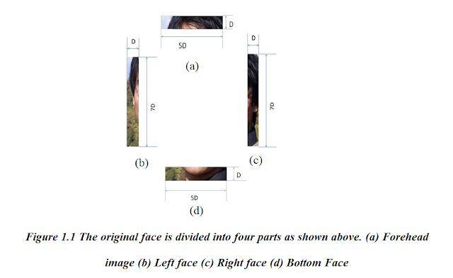
Canny Edge Detection is used to detect the edges. For the detection of edges of face region, a probable rectangle region including face is selected with the help of the separation of the eyes. If the separation between two eyes is ‘2D’ then the width of the probable rectangular region is defined to be ‘5D’ and the height is defined to be ‘8D’ as shown in Figure 1.0.
After the rectangular region is extracted, the rectangle is divided into four parts: forehead of dimension (5D x D), left face of dimension (D x 7D), right face of dimension (D x 7D), and
bottom face of dimension (5D x D) as shown in Figure 1.1.

 Then, in each of the above parts, Canny Edge Detection is applied. The final result is shown in Figure 1.2.

Below is the java code for finding Canny Edge(I didn't code it) :
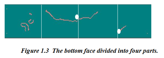
The two images i.e. forehead image and bottom face image are divided vertically into four parts. Each divided certainly cuts out edges. The divided region of bottom face is shown in Figure 1.3.
The output of Canny Edge Detection of four parts of face image contains many edges including weak and strong edges. We are only interested with the long and strong edges. For the detection of such long edges we have performed following steps:
Step 1:
Step 2:
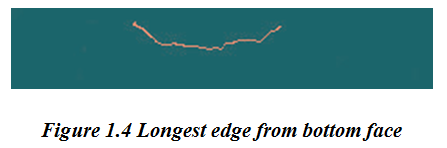
Edge is grown from the point of intersection with the boundary. In this algorithm, the edge is followed from left to right. The edge is considered to be a strong edge if its length is greater than a threshold length, T.
Step 3:
Weak edges are removed. The image obtained after removal of weak edges is shown in Figure 1.4.
Step 4:
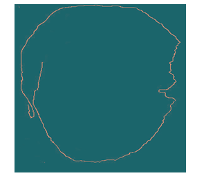
The same process is applied to all four parts. The same process is applied to the left and right regions, but the regions are divided according to the height. The final probable edge image is shown in Figure 1.5.

Step 5:
After the probable edge maps are found out using canny edge detection, all the edges are linked together using either “Hough Transform” or “Active Contour Model”. See Figure 1.6 for final output :
This is all about how to get the face edge boundary using Canny Edge Detection.
In my next blog I will write about extracting face region using Snake Algorithm.
Don't miss any news about your favorite topic.
Personalize your app.
Check out NTyles.
Get it on....
In my previous post I discussed more about Lucene basics. I will be discussing about them in future posts too. But this post is going to be totally different. I am bit moving towards Image Processing. So guys lets process our faces.
During my final year of Computer Engineering me along with other three guys did a project entitled "FACE REPLACEMENT SYSTEM". Face Replacement System is a semi-automatic software system which can be used to replace face of one person(target face) with that of another person(source face) in a photograph.
In the project Face Replacement System, my major role was to extract face region (face boundary) from photograph. So in this post I will be more discussing about Face Boundary Region Extraction. Face boundary region extraction is the process of detecting the face region in an image.
The face replacement system project lead us to the finding of three main algorithms for finding the Face Boundary of the face. They are:
- Skin Color Thresholding.
- Canny Edge Detection.
- Adaptive active contour model (Snake Algorithm).
CANNY EDGE DETECTION
Edge Detection is another method of face region extraction. The basic idea is to detect edges around the face so that the boundary around the face can be extracted. The edge detection process consists of two phases:
i. Canny Edge Detection
ii. Longest Edge Detectio
i. Canny Edge Detection
Canny Edge Detection is one of the most popular edge detection techniques. Detecting edges in an image filters out useless information. The Canny Edge Algorithm uses two thresholds, high and low thresholds. The value of low threshold is (0.4 x (high threshold)). The two values of thresholds are used to distinguish between strong and weak edges by the values of strength of the edges. To find the strength of edges, longest edge detection algorithm is used. Also the weak edge length is considered if and only if they are connected with the long edges. The output of Canny Edge Detection is a binary image. This binary image is regarded as the edge map for our face contour extraction algorithm.
Canny Edge Detection is used to detect the edges. For the detection of edges of face region, a probable rectangle region including face is selected with the help of the separation of the eyes. If the separation between two eyes is ‘2D’ then the width of the probable rectangular region is defined to be ‘5D’ and the height is defined to be ‘8D’ as shown in Figure 1.0.
After the rectangular region is extracted, the rectangle is divided into four parts: forehead of dimension (5D x D), left face of dimension (D x 7D), right face of dimension (D x 7D), and
bottom face of dimension (5D x D) as shown in Figure 1.1.


Below is the java code for finding Canny Edge(I didn't code it) :
/* * To change this template, choose Tools | Templates * and open the template in the editor. */ package Image; import java.awt.image.BufferedImage; import java.util.Arrays; /** * This software has been released into the public domain. * Please read the notes in this source file for additional information. * * * This class provides a configurable implementation of the Canny edge * detection algorithm. This classic algorithm has a number of shortcomings, * but remains an effective tool in many scenarios. This class is designed * for single threaded use only. * * Sample usage: * *ii. Longest Edge Detection* * For a more complete understanding of this edge detector's parameters * consult an explanation of the algorithm. * * @author Tom Gibara * */ public class CannyEdgeDetector { // statics private final static float GAUSSIAN_CUT_OFF = 0.005f; private final static float MAGNITUDE_SCALE = 100F; private final static float MAGNITUDE_LIMIT = 1000F; private final static int MAGNITUDE_MAX = (int) (MAGNITUDE_SCALE * MAGNITUDE_LIMIT); // fields private int height; private int width; private int picsize; private int[] data; private int[] magnitude; private BufferedImage sourceImage; private BufferedImage edgesImage; private float gaussianKernelRadius; private float lowThreshold; private float highThreshold; private int gaussianKernelWidth; private boolean contrastNormalized; private float[] xConv; private float[] yConv; private float[] xGradient; private float[] yGradient; // constructors /** * Constructs a new detector with default parameters. */ public CannyEdgeDetector() { lowThreshold = 2.5f; highThreshold = 7.5f; gaussianKernelRadius = 2f; gaussianKernelWidth = 16; contrastNormalized = false; } // accessors /** * The image that provides the luminance data used by this detector to * generate edges. * * @return the source image, or null */ public BufferedImage getSourceImage() { return sourceImage; } /** * Specifies the image that will provide the luminance data in which edges * will be detected. A source image must be set before the process method * is called. * * @param image a source of luminance data */ public void setSourceImage(BufferedImage image) { sourceImage = image; } /** * Obtains an image containing the edges detected during the last call to * the process method. The buffered image is an opaque image of type * BufferedImage.TYPE_INT_ARGB in which edge pixels are white and all other * pixels are black. * * @return an image containing the detected edges, or null if the process * method has not yet been called. */ public BufferedImage getEdgesImage() { return edgesImage; } /** * Sets the edges image. Calling this method will not change the operation * of the edge detector in any way. It is intended to provide a means by * which the memory referenced by the detector object may be reduced. * * @param edgesImage expected (though not required) to be null */ public void setEdgesImage(BufferedImage edgesImage) { this.edgesImage = edgesImage; } /** * The low threshold for hysteresis. The default value is 2.5. * * @return the low hysteresis threshold */ public float getLowThreshold() { return lowThreshold; } /** * Sets the low threshold for hysteresis. Suitable values for this parameter * must be determined experimentally for each application. It is nonsensical * (though not prohibited) for this value to exceed the high threshold value. * * @param threshold a low hysteresis threshold */ public void setLowThreshold(float threshold) { if (threshold < 0) throw new IllegalArgumentException(); lowThreshold = threshold; } /** * The high threshold for hysteresis. The default value is 7.5. * * @return the high hysteresis threshold */ public float getHighThreshold() { return highThreshold; } /** * Sets the high threshold for hysteresis. Suitable values for this * parameter must be determined experimentally for each application. It is * nonsensical (though not prohibited) for this value to be less than the * low threshold value. * * @param threshold a high hysteresis threshold */ public void setHighThreshold(float threshold) { if (threshold < 0) throw new IllegalArgumentException(); highThreshold = threshold; } /** * The number of pixels across which the Gaussian kernel is applied. * The default value is 16. * * @return the radius of the convolution operation in pixels */ public int getGaussianKernelWidth() { return gaussianKernelWidth; } /** * The number of pixels across which the Gaussian kernel is applied. * This implementation will reduce the radius if the contribution of pixel * values is deemed negligable, so this is actually a maximum radius. * * @param gaussianKernelWidth a radius for the convolution operation in * pixels, at least 2. */ public void setGaussianKernelWidth(int gaussianKernelWidth) { if (gaussianKernelWidth < 2) throw new IllegalArgumentException(); this.gaussianKernelWidth = gaussianKernelWidth; } /** * The radius of the Gaussian convolution kernel used to smooth the source * image prior to gradient calculation. The default value is 16. * * @return the Gaussian kernel radius in pixels */ public float getGaussianKernelRadius() { return gaussianKernelRadius; } /** * Sets the radius of the Gaussian convolution kernel used to smooth the * source image prior to gradient calculation. * * @return a Gaussian kernel radius in pixels, must exceed 0.1f. */ public void setGaussianKernelRadius(float gaussianKernelRadius) { if (gaussianKernelRadius < 0.1f) throw new IllegalArgumentException(); this.gaussianKernelRadius = gaussianKernelRadius; } /** * Whether the luminance data extracted from the source image is normalized * by linearizing its histogram prior to edge extraction. The default value * is false. * * @return whether the contrast is normalized */ public boolean isContrastNormalized() { return contrastNormalized; } /** * Sets whether the contrast is normalized * @param contrastNormalized true if the contrast should be normalized, * false otherwise */ public void setContrastNormalized(boolean contrastNormalized) { this.contrastNormalized = contrastNormalized; } // methods public void process() { width = sourceImage.getWidth(); height = sourceImage.getHeight(); picsize = width * height; initArrays(); readLuminance(); if (contrastNormalized) normalizeContrast(); computeGradients(gaussianKernelRadius, gaussianKernelWidth); int low = Math.round(lowThreshold * MAGNITUDE_SCALE); int high = Math.round( highThreshold * MAGNITUDE_SCALE); performHysteresis(low, high); thresholdEdges(); writeEdges(data); } // private utility methods private void initArrays() { if (data == null || picsize != data.length) { data = new int[picsize]; magnitude = new int[picsize]; xConv = new float[picsize]; yConv = new float[picsize]; xGradient = new float[picsize]; yGradient = new float[picsize]; } } //NOTE: The elements of the method below (specifically the technique for //non-maximal suppression and the technique for gradient computation) //are derived from an implementation posted in the following forum (with the //clear intent of others using the code): // http://forum.java.sun.com/thread.jspa?threadID=546211&start=45&tstart=0 //My code effectively mimics the algorithm exhibited above. //Since I don't know the providence of the code that was posted it is a //possibility (though I think a very remote one) that this code violates //someone's intellectual property rights. If this concerns you feel free to //contact me for an alternative, though less efficient, implementation. private void computeGradients(float kernelRadius, int kernelWidth) { //generate the gaussian convolution masks float kernel[] = new float[kernelWidth]; float diffKernel[] = new float[kernelWidth]; int kwidth; for (kwidth = 0; kwidth < kernelWidth; kwidth++) { float g1 = gaussian(kwidth, kernelRadius); if (g1 <= GAUSSIAN_CUT_OFF && kwidth >= 2) break; float g2 = gaussian(kwidth - 0.5f, kernelRadius); float g3 = gaussian(kwidth + 0.5f, kernelRadius); kernel[kwidth] = (g1 + g2 + g3) / 3f / (2f * (float) Math.PI * kernelRadius * kernelRadius); diffKernel[kwidth] = g3 - g2; } int initX = kwidth - 1; int maxX = width - (kwidth - 1); int initY = width * (kwidth - 1); int maxY = width * (height - (kwidth - 1)); //perform convolution in x and y directions for (int x = initX; x < maxX; x++) { for (int y = initY; y < maxY; y += width) { int index = x + y; float sumX = data[index] * kernel[0]; float sumY = sumX; int xOffset = 1; int yOffset = width; for(; xOffset < kwidth ;) { sumY += kernel[xOffset] * (data[index - yOffset] + data[index + yOffset]); sumX += kernel[xOffset] * (data[index - xOffset] + data[index + xOffset]); yOffset += width; xOffset++; } yConv[index] = sumY; xConv[index] = sumX; } } for (int x = initX; x < maxX; x++) { for (int y = initY; y < maxY; y += width) { float sum = 0f; int index = x + y; for (int i = 1; i < kwidth; i++) sum += diffKernel[i] * (yConv[index - i] - yConv[index + i]); xGradient[index] = sum; } } for (int x = kwidth; x < width - kwidth; x++) { for (int y = initY; y < maxY; y += width) { float sum = 0.0f; int index = x + y; int yOffset = width; for (int i = 1; i < kwidth; i++) { sum += diffKernel[i] * (xConv[index - yOffset] - xConv[index + yOffset]); yOffset += width; } yGradient[index] = sum; } } initX = kwidth; maxX = width - kwidth; initY = width * kwidth; maxY = width * (height - kwidth); for (int x = initX; x < maxX; x++) { for (int y = initY; y < maxY; y += width) { int index = x + y; int indexN = index - width; int indexS = index + width; int indexW = index - 1; int indexE = index + 1; int indexNW = indexN - 1; int indexNE = indexN + 1; int indexSW = indexS - 1; int indexSE = indexS + 1; float xGrad = xGradient[index]; float yGrad = yGradient[index]; float gradMag = hypot(xGrad, yGrad); //perform non-maximal supression float nMag = hypot(xGradient[indexN], yGradient[indexN]); float sMag = hypot(xGradient[indexS], yGradient[indexS]); float wMag = hypot(xGradient[indexW], yGradient[indexW]); float eMag = hypot(xGradient[indexE], yGradient[indexE]); float neMag = hypot(xGradient[indexNE], yGradient[indexNE]); float seMag = hypot(xGradient[indexSE], yGradient[indexSE]); float swMag = hypot(xGradient[indexSW], yGradient[indexSW]); float nwMag = hypot(xGradient[indexNW], yGradient[indexNW]); float tmp; /* * An explanation of what's happening here, for those who want * to understand the source: This performs the "non-maximal * supression" phase of the Canny edge detection in which we * need to compare the gradient magnitude to that in the * direction of the gradient; only if the value is a local * maximum do we consider the point as an edge candidate. * * We need to break the comparison into a number of different * cases depending on the gradient direction so that the * appropriate values can be used. To avoid computing the * gradient direction, we use two simple comparisons: first we * check that the partial derivatives have the same sign (1) * and then we check which is larger (2). As a consequence, we * have reduced the problem to one of four identical cases that * each test the central gradient magnitude against the values at * two points with 'identical support'; what this means is that * the geometry required to accurately interpolate the magnitude * of gradient function at those points has an identical * geometry (upto right-angled-rotation/reflection). * * When comparing the central gradient to the two interpolated * values, we avoid performing any divisions by multiplying both * sides of each inequality by the greater of the two partial * derivatives. The common comparand is stored in a temporary * variable (3) and reused in the mirror case (4). * */ if (xGrad * yGrad <= (float) 0 /*(1)*/ ? Math.abs(xGrad) >= Math.abs(yGrad) /*(2)*/ ? (tmp = Math.abs(xGrad * gradMag)) >= Math.abs(yGrad * neMag - (xGrad + yGrad) * eMag) /*(3)*/ && tmp > Math.abs(yGrad * swMag - (xGrad + yGrad) * wMag) /*(4)*/ : (tmp = Math.abs(yGrad * gradMag)) >= Math.abs(xGrad * neMag - (yGrad + xGrad) * nMag) /*(3)*/ && tmp > Math.abs(xGrad * swMag - (yGrad + xGrad) * sMag) /*(4)*/ : Math.abs(xGrad) >= Math.abs(yGrad) /*(2)*/ ? (tmp = Math.abs(xGrad * gradMag)) >= Math.abs(yGrad * seMag + (xGrad - yGrad) * eMag) /*(3)*/ && tmp > Math.abs(yGrad * nwMag + (xGrad - yGrad) * wMag) /*(4)*/ : (tmp = Math.abs(yGrad * gradMag)) >= Math.abs(xGrad * seMag + (yGrad - xGrad) * sMag) /*(3)*/ && tmp > Math.abs(xGrad * nwMag + (yGrad - xGrad) * nMag) /*(4)*/ ) { magnitude[index] = gradMag >= MAGNITUDE_LIMIT ? MAGNITUDE_MAX : (int) (MAGNITUDE_SCALE * gradMag); //NOTE: The orientation of the edge is not employed by this //implementation. It is a simple matter to compute it at //this point as: Math.atan2(yGrad, xGrad); } else { magnitude[index] = 0; } } } } //NOTE: It is quite feasible to replace the implementation of this method //with one which only loosely approximates the hypot function. I've tested //simple approximations such as Math.abs(x) + Math.abs(y) and they work fine. private float hypot(float x, float y) { return (float) Math.hypot(x, y); } private float gaussian(float x, float sigma) { return (float) Math.exp(-(x * x) / (2f * sigma * sigma)); } private void performHysteresis(int low, int high) { //NOTE: this implementation reuses the data array to store both //luminance data from the image, and edge intensity from the processing. //This is done for memory efficiency, other implementations may wish //to separate these functions. Arrays.fill(data, 0); int offset = 0; for (int y = 0; y < height; y++) { for (int x = 0; x < width; x++) { if (data[offset] == 0 && magnitude[offset] >= high) { follow(x, y, offset, low); } offset++; } } } private void follow(int x1, int y1, int i1, int threshold) { int x0 = x1 == 0 ? x1 : x1 - 1; int x2 = x1 == width - 1 ? x1 : x1 + 1; int y0 = y1 == 0 ? y1 : y1 - 1; int y2 = y1 == height -1 ? y1 : y1 + 1; data[i1] = magnitude[i1]; for (int x = x0; x <= x2; x++) { for (int y = y0; y <= y2; y++) { int i2 = x + y * width; if ((y != y1 || x != x1) && data[i2] == 0 && magnitude[i2] >= threshold) { follow(x, y, i2, threshold); return; } } } } private void thresholdEdges() { for (int i = 0; i < picsize; i++) { data[i] = data[i] > 0 ? -1 : 0xff000000; } } private int luminance(float r, float g, float b) { return Math.round(0.299f * r + 0.587f * g + 0.114f * b); } private void readLuminance() { int type = sourceImage.getType(); if (type == BufferedImage.TYPE_INT_RGB || type == BufferedImage.TYPE_INT_ARGB) { int[] pixels = (int[]) sourceImage.getData().getDataElements(0, 0, width, height, null); for (int i = 0; i < picsize; i++) { int p = pixels[i]; int r = (p & 0xff0000) >> 16; int g = (p & 0xff00) >> 8; int b = p & 0xff; data[i] = luminance(r, g, b); } } else if (type == BufferedImage.TYPE_BYTE_GRAY) { byte[] pixels = (byte[]) sourceImage.getData().getDataElements(0, 0, width, height, null); for (int i = 0; i < picsize; i++) { data[i] = (pixels[i] & 0xff); } } else if (type == BufferedImage.TYPE_USHORT_GRAY) { short[] pixels = (short[]) sourceImage.getData().getDataElements(0, 0, width, height, null); for (int i = 0; i < picsize; i++) { data[i] = (pixels[i] & 0xffff) / 256; } } else if (type == BufferedImage.TYPE_3BYTE_BGR) { byte[] pixels = (byte[]) sourceImage.getData().getDataElements(0, 0, width, height, null); int offset = 0; for (int i = 0; i < picsize; i++) { int b = pixels[offset++] & 0xff; int g = pixels[offset++] & 0xff; int r = pixels[offset++] & 0xff; data[i] = luminance(r, g, b); } } else { throw new IllegalArgumentException("Unsupported image type: " + type); } } private void normalizeContrast() { int[] histogram = new int[256]; for (int i = 0; i < data.length; i++) { histogram[data[i]]++; } int[] remap = new int[256]; int sum = 0; int j = 0; for (int i = 0; i < histogram.length; i++) { sum += histogram[i]; int target = sum*255/picsize; for (int k = j+1; k <=target; k++) { remap[k] = i; } j = target; } for (int i = 0; i < data.length; i++) { data[i] = remap[data[i]]; } } private void writeEdges(int pixels[]) { //NOTE: There is currently no mechanism for obtaining the edge data //in any other format other than an INT_ARGB type BufferedImage. //This may be easily remedied by providing alternative accessors. if (edgesImage == null) { edgesImage = new BufferedImage(width, height, BufferedImage.TYPE_INT_ARGB); } edgesImage.getWritableTile(0, 0).setDataElements(0, 0, width, height, pixels); } }* //create the detector * CannyEdgeDetector detector = new CannyEdgeDetector(); * //adjust its parameters as desired * detector.setLowThreshold(0.5f); * detector.setHighThreshold(1f); * //apply it to an image * detector.setSourceImage(frame); * detector.process(); * BufferedImage edges = detector.getEdgesImage(); *
The two images i.e. forehead image and bottom face image are divided vertically into four parts. Each divided certainly cuts out edges. The divided region of bottom face is shown in Figure 1.3.
The output of Canny Edge Detection of four parts of face image contains many edges including weak and strong edges. We are only interested with the long and strong edges. For the detection of such long edges we have performed following steps:
Step 1:

Step 2:
Edge is grown from the point of intersection with the boundary. In this algorithm, the edge is followed from left to right. The edge is considered to be a strong edge if its length is greater than a threshold length, T.
Step 3:
Weak edges are removed. The image obtained after removal of weak edges is shown in Figure 1.4.

Step 4:
The same process is applied to all four parts. The same process is applied to the left and right regions, but the regions are divided according to the height. The final probable edge image is shown in Figure 1.5.

Step 5:
After the probable edge maps are found out using canny edge detection, all the edges are linked together using either “Hough Transform” or “Active Contour Model”. See Figure 1.6 for final output :
 |
| Figure 1.6 : Result after active contour Model. |
This is all about how to get the face edge boundary using Canny Edge Detection.
In my next blog I will write about extracting face region using Snake Algorithm.
No comments:
Post a Comment